I struggled with this month’s entry like maybe never before, not in the typical missing muse lack of a starting point way, but in the how a recent entry was about missed opportunity and how I have spoken to loss driven by the very happenstance I am about to lament in a prior entry.
It was with reminding myself that one of the parallel intention’s of this weblog is to share and put forth the notion that Bridgewrighting is a continuing trade, one that requires nurturing both in a growing understanding of this fact by the engineering and wooden bridge communities and in interested members of the general public – and with that, a hope to incentivize a continuing stream of up and coming practitioners into our fold.
That coupled with the thought that this most recently squandered opportunity is like no other to unfold in our lifetimes, had me quash the thought that I would again be beating a dead horse.
The allied trades I practice, Timberframing & Bridgewrighting, were for a time briefly lost. In those years which slipped by with few or no practitioners, vast amounts of information, everyday information so seemingly mundane that few thought to describe it in written words, was also lost. This body of information largely existed in the form of a workaday hive-like storehouse found in the minds of everyday practitioners. It left us with them, slipping into oblivion with those minds no longer being asked to share their depths of understanding and then, as these individuals slowly slipped away, their insights, their once shining light was likewise slowly extinguished and also passed out of being. This is continuously driven home to me in the practicing of both of these trades long enough now to have borne witness to a slow reawakening. In the last thirty years, much has been derived and revived, through research and in a growing understanding of historic example. That reawakening yet unfolds and there is a growing determination amongst today’s practitioners that this body of knowledge, this once faded brilliance, will not be and must never be, lost again. The opportunity lost this go is the replication of a bridge which was to the North American Timberframing Community among the greatest of timber works to be seen. For many in this community, this construction was a built heritage pilgrimage, a must-see somewhat akin to Chartres, the Parthenon or Pont du Gard. I have spoken to this bridge in a number of entries. The bridge about to be replicated is the once mighty Blenheim.

This Public Domain image of Van Gogh’s Grieving Old Man – Trauernder Alter Mann – At Eternity’s Gate – 1890 Oil on canvas completed in the closing months of his life while he was recuperating in the asylum at St. Rémy – Is used here at the courtesy of Wikimedia Commons
The aspect of this opportunity which is lost is how the framing of the new Blenheim is to be executed not by a highly skilled crew of Bridgewrighting savvy Carpenters, but by a robot. Gone is the opportunity this massive project afforded for trained Bridgewrights to share their knowledge with up and comers in the successive time-honored Master to Apprentice way such methodologies have been passed forward for millennia.
Let’s put aside the seeming absurdity of executing a historic replication with a robot. My point as always is that if we are to perpetuate this skilled trade, the requisite is that we have practitioners sharing their expertise in the practice of those skills. A robot does not share and I’m none so sure one can reasonably replace a group of skilled Bridgewrights.
Do not take what I am about to say as a Luddite-like blanket condemnation of an automated CNC computer-driven approach to timberframing, far simpler frames are obviously doable with this technology. My opinion is more practical and Bridgewrighting specific than that. While CNC is hugely efficient at producing multiple copies of the same piece over and over again, and such pieces do exist in this bridge in limited quantities, (Wind Bracing) major sub-assemblies like the Trusses and Lateral Bracing systems were and are, for good reason (Camber) typically scribed. This is because there are subtle changes in the lengths of Braces and Counter Braces and in Lateral Brace shoulder angle from panel to panel, meaning these are compound cuts with shifting angles from one set to the next, or even from one end to the other, driven by the attitude of the Ties and their relationship to the changes in the inclination of camber along the spans length, (Camber is not a constant and perfect radii, this is a variable, which changes from panel to panel) there are slight changes in length in successive panels with a truss’es Braces and Counter Braces. These changes need be accounted for to develop camber and ensure necessary full bearing proper fit, but in some panels, these changes in length and angle(s) of intersection are so subtle as to seem hardly worth mathematically predicting. Such running of the numbers in this morphing geometry being necessary to program a computer-controlled robot to fabricate subtly dissimilar pieces literally removes all advantage from a CNC type approach in bridge framing. Or worse the subtleties of slightly shifting compound angles and lengths are lost to ignorance – I’ve never seen a set of drawings which acknowledged and quantified this camber driven phenomenon. Drawings are typically kept simple for ease and clarity. Camber is most often specified as a target rise at mid-span and the development of nuances and subtleties in the fine details in achieving that end have long been left to the Bridgewrights chosen.
That said, if full blown, every last detail CAD drawings are necessary to a CNC effort in executing the framing of a wooden through truss and the design engineer does not create them, who does? Will it be a CAD Draftsman steeped in the deep knowledge required to fully understand long clear-span joined wooden bridges, a wooden bridge professional? Or simply a tech in the employ of a factory.
Furthermore, wood in the form of timber is unlike those other materials CNC efforts typically manipulate. Paradoxically, while easy to work, wood always retains its organic nature, try as you might to mill out like copies. Bow and Wind (twist) and tensions released in the milling process will result in not insignificant variations, variations which simply cannot be reflected in CAD drawings.
Add levels of complexity to milled timber like those found in The Blenheim, Joggled Posts, forty foot Arch leafs, crippled Counter Braces interrupted by an encased Shear Block joined triple Solid Timber Arch in the taller middle truss, Bottom Chord Lams with multiple Daps along their length and Bolt ‘O Lightning tension splices at either end, and these organic variations will be even greater and hold greater challenge.
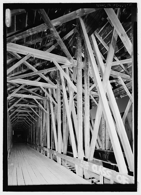
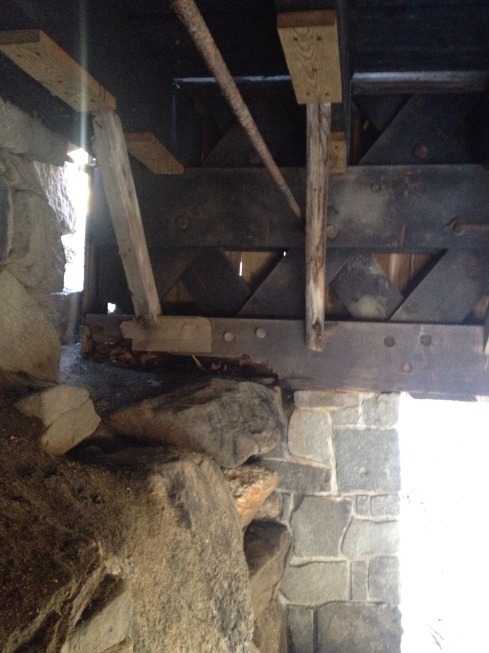
The interwoven complexity of The Blenheim was captured in this image taken just shy of mid span – This photo by Jet Lowe, taken just seven years before an unknowing storm almost erased an underrealized bit of heritage is seen here as a courtesy of the Historic American Engineering Record and the Library of Congress
Historically, timber trusses in bridges, industrial spaces, and public buildings saw the timber joinery within them cut to a far greater level of precision than that found in common structures. In any timber truss and most notably in Bridge Trusses, a load is imparted and conveyed from mid-span to abutment, from panel to panel, not simply through the timber in the truss-work, member by member. When you get down to the heart of it these load paths are the joinery, bearing surface to bearing surface within that timber truss-work. In the instance of the Blenheim, literally hundreds of bearing surfaces. This is why truss-work was typically executed with far greater care than more pedestrian constructions, any truss’es joint which fails to have hard up full bearing will result in undue and unintended crush of wood fiber resulting in changes in intended target geometry. An accumulation of such crush leads to loss of camber and this to shifting load paths, with loads being transferred in ways never intended.
To my mind, it is not enough that this replication approximates its predecessor in appearance. The Blenheim and Powers’ and Long’s (More information on both of these gentlemen can be found by entering their names in the search bar above) structural design will not be honored if the bearing surfaces are not well cut. That statement being made, CNC fabricated timber frames do not have a reputation of being high-tolerance frames in the timber framing industry and this is to be an effort to replicate one of the more complicated bridge truss types on what was the longest existing two hundred foot plus joined timber truss bridge history left to us.
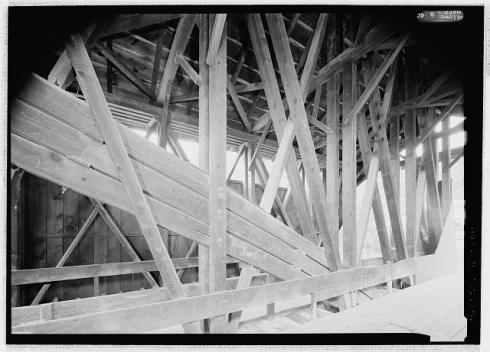
The “Encased Arch” in the taller middle truss – This photo is seen here as a courtesy of Library of Congress and the Historic American Engineering Record – Photographed in 2004 by Jet Lowe
This potential in crush and distorting geometry is perhaps of particular concern with a Blenheim replication, being that this “Double-Barreled” bridge holds a unique structural detail in the form of its massive Encased Arch in the taller middle truss. I’ve always seen this single Arch in the middle truss as part of Powers’ genius, (Outboard Arch ends on less than properly maintained examples sometimes suffer over time from the collection of leaf litter on them where they join the masonry Abutments, add to that water leaks in the siding and…) keeping the Arch ends as protected from the weather as possible is hugely beneficial though does demand a Powers like level of precision in the execution of the joinery, particularly in the two outboard trusses. Of the three trusses, the middle truss is behaviorally very different from the other two and will carry twice the live and dead loads than that of the two outboard trusses. Should crush borne distortions in truss geometry come to pass, unbalanced loads will potentially shift to the far stiffer Arch which will not distort like the adjacent framing. (Crush borne distortions shifting load to a stiffer arch and this unbalanced load potential would be far less of a worry were this but two like trusses.) This Arch, the backbone of this bridge, is also potentially it’s Achilles Heel.

The Arch rises up and kisses the Top Chord at mid span – This photo is seen here as courtesy of The Library of Congress and the Historic American Engineering Record – Photographed in 2004 by Jet Lowe
Scribe Layout without question remains the most efficient approach to wooden bridge framing, with such approach, dimensional variation, bow and wind, and changing lengths and angles needn’t be identified and mathematically quantified, they are simply dealt with in real world conditions. This is not simply my opinion. It is a demonstrable truth, and the reason why wooden bridges were the last bastion of scribe type timber layout right through to the end of their common era of construction, better than a full century after scribe layout was abandoned for most all other timber constructions.

This bridge stood as one of our Nation’s Built Heritage masterworks – This photo of it is seen here as courtesy of The Library of Congress and the Historic American Engineering Record – Photographed in 2004 by Jet Lowe
So I find myself again grieving for the Mighty Blenheim, though this time not for what once was, but for the ironic opportunity its loss afforded in the form of a baton of knowledge to be handed off and with that, the shared understandings which may have been found in the day to day demands of replicating one of America’s timber masterworks. Sadly, neither will come to pass.
All this is part of the fading brilliance in what might,
nay, what should have been.